| Sr. No. | KVA | Impedance % | Maximum Total Loss (W) @ 75˚ Celsius | |||||
| LEVEL 1 | LEVEL 2 | LEVEL 3 | ||||||
| 50% | 100% | 50% | 100% | 50% | 100% | |||
| 1 | 250 | 4.5 | 1050 | 3150 | 980 | 2930 | 920 | 2700 |
| 2 | 315 | 4.5 | 1100 | 3275 | 1025 | 3100 | 955 | 2750 |
| 3 | 400 | 4.5 | 1300 | 3875 | 1225 | 3450 | 1150 | 3330 |
| 4 | 500 | 4.5 | 1600 | 4750 | 1510 | 4300 | 1430 | 4100 |
| 5 | 630 | 4.5 | 2000 | 5855 | 1860 | 5300 | 1745 | 4850 |
| 6 | 800 | 5.0 | 2459 | 7300 | 2287 | 6402 | 2147 | 5837 |
| 7 | 1000 | 5.0 | 3000 | 9000 | 2790 | 7700 | 2620 | 7000 |
| 8 | 1250 | 5.0 | 3600 | 10750 | 3300 | 9200 | 3220 | 8400 |
| 9 | 1600 | 6.25 | 4500 | 13500 | 4200 | 11800 | 3970 | 11300 |
| 10 | 2000 | 6.25 | 5400 | 17000 | 5050 | 15000 | 4790 | 14100 |
| 11 | 2500 | 6.25 | 6500 | 20000 | 6150 | 18500 | 5900 | 17500 |
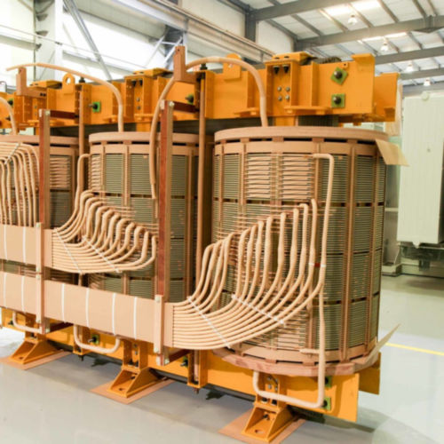
Power Transformer
Power transformers are designed to be used for step-up and step down the application in the transmission network of higher voltages like 400 kV, 220 kV, 110 kV, 66 kV, 33kV, etc.
The designing make the transformers 100% efficient in transmitting heavy load and high voltage i.e., higher than 33 KV. If compared to the size of the distribution transformers, these transformers are bigger and are used in transmission substation, generating station and application areas requiring high insulation level.
We produce power electrical transformers of capacity up to 50 MVA, 3 Phase, up to 132 KV Class, ONAN/ONAF/OFAF/OFWF Cooling. Our transformers are popular for its trouble-free long performance, reliability and very competitive prices.
Features Of Power Transformer
- Designed for 25 years of trouble-free performance.
- Design conforms to IS 2026, IEC 60076, ANSI and other relevant standards.
- Low power loss and low noise.
- Designed to withstand electrical impulses and thermal and dynamic stresses.
- Optimum utilization of active materials for compactness.
- Modern manufacturing techniques ensure cost effectiveness and reliability.