
Furnace Transformer
Furnace Transformers are designed for induction melting and induction heating for ferrous and non-ferrous metal.
Induction Furnace has coil constructed from heavy copper tubing. it is designed and turned to the inverter circuit which applies a medium frequency (generally 500 Hz or 1000 Hz) voltage to the induction coil. The magnetic field produced by the induction coil induces eddy currents in the charge and heats it. Medium frequency is necessary to enhance the rate of heat generation.
- Indoor/ Outdoor Pad Mounted
- On Load / Off Load Transformer
Features Of Furnace Transformer
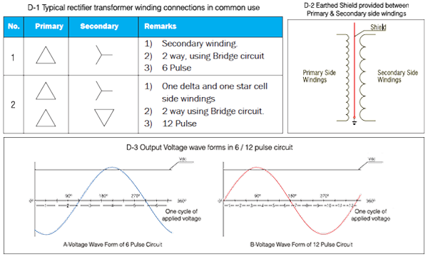
- Electrostatic earth shield provided between primary and secondary side windings for protection of rectifier elements against voltage surges in primary side windings. (Ref. D-2)
- Use reduced current densities to limit losses due to harmonic currents.
- Use reduced flux density to limit core losses due to harmonic flux.
- Designed to suit 6 Pulse / 12 Pulse or other rectifier circuits as required by furnace manufacturer. Two active parts in one tank can also be provided.
- Confirming to I.S. 2026 and I.S. 4540 – specifications for power transformer and specifications for rectifiers.
Technical Specifications
| Type | Indoor/ Outdoor Pad Mounted |
|---|---|
| Duty | On Load / Off Load |
| Voltage Class | 3.3, 6.6, 11, 22, 33 Kv or special class by customer |
| Vector Group | Dyn11, Dyn5, Dyn1 or other specified by customer |
| No. of phase | 3 phases |
| Frequency | 50/60 Hz |
| Tap Range | ±10% in on load and ±7.5% in off load or other specified by customer. |
| Winding Material | Copper with multiple paper covering |
| Applicable Standards | IS-2026, IEC 60076 |
| Painting | Epoxy, Polyurethane or specified by customer |
| Type | Indoor/ Outdoor Pad Mounted |
|---|---|
| Voltage Class | 3.3,6.6, 11, 22, 33 Kv or special class by customer |
| Vector Group | Dyn11, Dyn5, Dyn1 or other specified by customer |
| No. of phase | 3 phases |
| Frequency | 50/60 Hz |
| Tap Range | ±10 %, +5% To -15% in 1.25% steps in 17 position or in 2.5% steps in 9 Positions or as per requirement of customer. |
| Winding Material | Copper with multiple paper covering |
| Applicable Standards | BIS-1180, IS-2026, IEC 60076 |
| Painting | Epoxy, Polyurethane or specified by customer |
Why weight and dimensions of induction furnace transformers are higher than conventional transformer?
- To achieve reduced current densities, more conductor cross-section areas are required, Hence core weight increases.
- To achieve reduced flux density, more core cross-section are is required, hence core weight increases.
- In a transformer, core weight and copper weight are inter dependent. Increase in conductor cross-section requires that core window is bigger resulting in the increase of core weight also. Similarly, an increase in core cross-section is achieved by increasing core dia. which increases mean Dias of winding and the lengths of their mean turn. This increases copper weight also, increase in core and copper weights increase the overall dimensions, increasing oil quantity, structural steel, etc.
- When an electrostatic shield is provided between the windings, more radial gap is required between the windings. This further increase core weight, copper weight, oil quantity and structural steel.