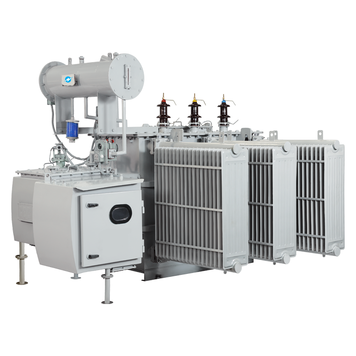
On Load Distribution Transformer

We manufacture ISI approved onload distribution transformer starting from 250 KVA to 2500 KVA under BIS-1180(Jan 2016) and above 2500 KVA up-to 5000 KVA under IS-2026 of all voltage class and covering all level of efficiency.

  • Designed for minimum 25 years for 24 x 7 duty with negligible maintenance and silent operation.
  • Indoor/ Outdoor Pad Mounted
  • Copper Winding with multiple paper covering

Features Of On Load Transformer

  • Magnetic Circuit is made using step-lap design for lower losses and low magnetizing current of core by using high quality CRGO material with grades such as ZDKH, ZDMH, AMORPHOUS, MOH, etc.
  • Electric Circuit is made using electrolytic grade with 99.99% pure High Quality Copper from our regular and reputed vendor HINDALCO & STERLITE with Foil winding in L.V coil of transformer.
  • High Dielectric Insulation property to withstand lightening impulse and voltage surges.
  • ONAN through natural convection for effective cooling through axial and radial ducts.

Technical Specifications

Onload Transformers are installed where voltage fluctuations from h.v side are continuous. So onload transformer changes tap using AVR without any power-cut and give constant output voltage. Thus over-all power consumption of industry gets optimized hence results in power savings.
Type Indoor/ Outdoor Pad Mounted
Voltage Class 3.3,6.6, 11, 22, 33 Kv or special class by customer
Vector Group Dyn11, Dyn5, Dyn1 or other specified by customer
No. of phase 3 phases
Frequency 50/60 Hz
Tap Range ±10 %, +5% To -15% in 1.25% steps in 17 position or in
2.5% steps in 9 Positions or as per requirement of customer.
Winding Material Copper with multiple paper covering
Applicable Standards BIS-1180, IS-2026, IEC 60076
Painting Epoxy, Polyurethane or specified by customer

Standard Fittings

  • Rating & Diagram Plate
  • Earthing terminals
  • Lifting Lugs
  • Thermometer Pocket
  • Air Release Plug
  • Conservator Tank
  • Cover Mounted Thermometer
  • Explosion Vent With Suitable Diaphragm
  • Oil Level Indicator
  • Drain Cum Oil Filter Valve
  • Top Oil Filter Valve
  • Bi-Directional Roller
  • Silica gel breather
  • Cooling Radiators
  • H.V & L.V Side cable box with copper bus-bar
  • Neutral – earth bushing for earthing of neutral
  • RTCC panel for onload distribution transformer

Protective Devices

  • Buchholz Relay with alarm and trip contact for transformers from 500 KVA to 5000 KVA
  • Oil Temperature Indicator with alarm and trip contact for transformers from 630 KVA to 5000 KVA
  • Winding Temperature Indicator with alarm and trip contact for transformers from 800 KVA to 5000 KVA
  • Magnetic Oil Level gauge with alarm contact for transformers from 1250 KVA to 5000 KVA

Optional Accessories

  • Neutral C.T
  • Jacking Pads
  • Shut-off Valves
  • Annunciation/Inspection Window
  • Pressure Release Valve with contacts

Type Of Winding

  • For achieving losses as per BIS-1180 we have developed FOIL WINDING for L.V coil of the transformer. Following are main advantages of foil winding.
  • Temperature rise is lower due to high face-area for current flow
  • High Mechanical strength towards AXIAL and RADIAL forces in comparison to conventional layer winding.
  • Inter-turn Fault is vanished out due to foil winding as compare to layer winding
  • No need of transposition due to foil winding which gives exact results as compare to conventional winding.

Benefits

  • Due to on-load transformer the voltage at LV side remains in limit against the voltage fluctuations from HV side.
  • For changing a tap, shut down of factory is not reliable. But due to the on-load transformer, you can change tap even when your factory is running.
  • As there is RTCC panel with AVR (Automatic Voltage Regulator) LV side voltage remains in desire range by changing tap automatically.
  • Due to on-load transformer efficiency of transformer increases, losses of the transformer and other electrical equipment decreases results in low power consumption, and overall life of the transformer and other electrical equipment increases.

Maximum Total Losses Upto 11 Kv Class Transformers As Per BIS-1180

Sr. No. KVA Impedance % Maximum Total Loss (W) @ 75˚ Celsius
LEVEL 1 LEVEL 2 LEVEL 3
50% 100% 50% 100% 50% 100%
1 250 4.5 1050 3150 980 2930 920 2700
2 315 4.5 1100 3275 1025 3100 955 2750
3 400 4.5 1300 3875 1225 3450 1150 3330
4 500 4.5 1600 4750 1510 4300 1430 4100
5 630 4.5 2000 5855 1860 5300 1745 4850
6 800 5.0 2459 7300 2287 6402 2147 5837
7 1000 5.0 3000 9000 2790 7700 2620 7000
8 1250 5.0 3600 10750 3300 9200 3220 8400
9 1600 6.25 4500 13500 4200 11800 3970 11300
10 2000 6.25 5400 17000 5050 15000 4790 14100
11 2500 6.25 6500 20000 6150 18500 5900 17500
Menu